Use Case Diagrams
Actors and Use Cases in UML
The Unified Modelling Language provides a diagram type that can be used to model use case architecture at a high level. This use case diagram does not give any detail of the use cases themselves, and as such is not a very valuable diagram as far as a developer is concerned. However, it does give a high level view of which use cases are associated with which actors. If incorporated as part of a hyperlinked document, such as a web site, the diagram can serve as a visual contents page, each item appearing on the diagram hyperlinking to the detailed textual description of that element.
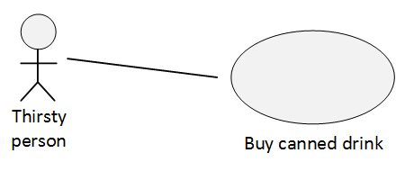
In a use case diagram, an actor is represented by a stick-person, and a use case by an ellipse. The connection between them is drawn as a line. The line indicates that the actor participates in that use case. There is no notation for indicating whether the actor is the initialtor of the use case or just a participant. To capture that detail, it would be necessary to look at the use case’s detailed description.
The diagram below shows the ‘thirsty person’ actor participating in the ‘buy canned drink’ use case:


Packages and Grouping
Since most systems have a significant number of use cases by the time all the requirements are captured, it is usually beneficial to group use cases into packages. A package is a collection of use cases that share a common purpose, that service a common persistent entity in a database, or that represent the collection of goals a particular actor has. The grouping mechanism allows us to better organise and understand the areas of functionality our system is required to have. It often leads on to high level architectural decisions that partition the implementation along similar lines.
There is a UML packaging notation that is used to draw enclosed regions around groups of use cases in a use case diagram. in reality though it is of more value just to organise the use case descriptions into families and put them into a named package. The notation is incidental.